Miracle Piano Guide - NES PC Serial Cable - Foot Switch Mod
Posted: Mon Mar 26, 2012 4:08 pm
Miracle Piano Guide - NES Cable - Foot Switch Mod
UPDATE - Added PC Cable Instructions in the 2nd Reply

The Miracle Piano came out in 1990 and can be hooked up to the NES, SNES, Genesis and computers to assist in learning how to play the piano. A custom serial cable for each console or computer communicates between the Piano and Console or PC to detect piano key presses and play back songs. This is an obscure Piano Keyboard that sometimes might be found online at a high price or a Rare chance discovery at a Thrift Store or Swap Meet. Surprisingly, the NES cart is more common then the piano keyboard, it can be found inexpensively online.
The Miracle Piano is no longer manufactured and can only be bought used. Sometimes the piano is missing the power supply, most of the time the Sustain Foot Pedal and proprietary serial communication cable is missing. In this Guide I will show how to replace the missing parts and build a custom Communication Serial Cable. I will focus on the NES, other systems can be built following the same procedure. At the end of the OP are references for other systems.
First a little background information on the Miracle Piano.
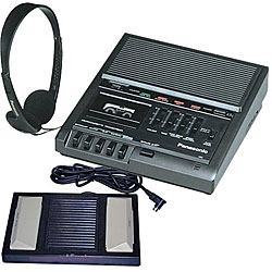
Here are pics of a new Miracle Piano in a box, you can see the Foam Foot Pedal and NES cable:
Extra Connections
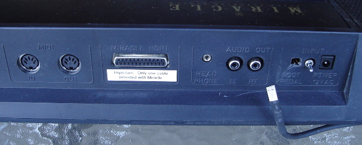
Here is what makes the Miracle Piano unique. The back has connections for Stereo RCA Audio out, Headphone Jack, Foot Pedal, Power Input, Midi In and Out and a proprietary 25 pin Serial connection. The Midi connections are standard and can be used with a PC or Mac to control the Piano. Play sounds, beats and songs controlled by the computer!
Power Supply
Any Power Supply that has AC 12 volt 1 Amp/1000 Milliamps output will do. The voltage must be 12 volt and the amperage can be higher but not lower. The AC voltage is uncommon, DC is the normal output on most power supplies.
Foot Pedal
The Foot Pedal connection allows a sustain feature in the Miracle Piano. The two prongs are very close to the power switch. Even if a sustain pedal is not added, a good idea to obtain a connector to prevent accidental shorting. The connector can be found at any electronics retailer such as Radio Shack or Frys. The square hole in the back of the piano is small. I had to file down the sides of a connector as well as opening up the hole a little in the back of the piano.
As for the Foot Pedal, any digital switch can be used that shorts the two prongs. Be sure it is not analog such as a game driving controller gas pedal. Switches can be found at music stores or a sewing machine foot switch or one can be built.
I already have a higher quality foot pedal at home, better then the original foam version. Anyone remember the Court Tape Recorder Foot Switch I bought a almost a year ago? I was going to make a Track and Field style controller out of it by gutting a PC keyboard encoder. Never did since it would have been for only a few games.
The pedal is perfect for the piano, but I had a concern. I'm almost positive the original Foot switch would just short the two prongs, but what if there is a resistor? Downloading the manual and schematics did not help, it took a brave YouTube poster to convince me. PAPERCLIPS?! 
Any switch that completes the connections of the two pins works just fine.
Okay the Court Data Recorder Foot Switch works, an easy cut the end and solder in the right plug from my local electrician store. I spliced in both limit switches so either foot pedal produces the sustain feature.
Custom Serial Cable
The Miracle Piano has a 25 pin Serial Port, strangely it is upside down compared to a normal position of connector with more pins on top. The upside down connection is an important point to identify which pins will be used for the custom cable. I knew the NES can be hooked up, a search of the specialized cable shows a little on the pricey side. I have plenty of spare NES controllers to rob the cable with the game console Plug. The rest of the parts can be found at the local Electrical Supply retailer.
1. NES Controller - For the cable assembly
2. 25 Pin Serial Male Connector - Exposed Pins
3. 25 Pin Serial Connector Housing - Plastic or Metal
4. Electrical Tape - Black matches the cable
5. Heat Shrink - Various sizes
6. Lighter - Barbecue Lighter works well
7. Solder and Soldering Iron
8. Zip Tie - If no lock screw in housing
9. MultiMeter - If 3rd party controller, 1st party described below
The serial connector can be the type that has preinstalled pins or the pins can be bought separately. Preinstalled pins are harder to solder, but since there are only four wires I went this route. The plastic screw in the bag anchors the cable so a Zip Tie is not needed.
The NES controller plug and cable will be used with the 25 pin serial connector. Either desolder the wires or just cut the cable at the NES controller end. Do not toss the vintage NES controller, it might come in handy for parts or a future mod.
Strip away about two inches of the insulation from the NES controller cable to expose the inner five wires, then strip a little off each wire. If a 3rd party controller is cannibalized, the wire colors might be different. To be sure of the connections, a good idea to test each wire with a MultiMeter to verify the pin locations.

Looking towards the NES console as if connected, the pins are laid out with four on the left and three on the right. The NES connector pins for a 1st party Nintendo controller read starting from the TOP LEFT, note the top right has a larger number.
Left Side From Top
Pin 1 - Brown
Pin 2 - Red
Pin 3 - Orange
Pin 4 - Yellow
Right Side From Top
Pin 7 - White
Pin 6 - No Wire
Pin 5 - No Wire

The serial connector housing is designed for a twenty five wire lead, so the NES five wire cable has to be made thicker. Make sure this is done before soldering any wires. Electrical tape can be used, but heat shrink offers a cleaner look.
Place an initial small wrap of Electrical Tape to make the cable thicker. Follow thru by covering with Heat Shrink. Use the Lighter to reduce the size of the Heat Shrink. Add a layer and heat each layer one at a time, use a larger sized Heat Shrink if needed. When completed the insulation should be the same thickness as the connector housing cable hole.
Solder the wires
Check and double check the pin locations. There are thirteen pins on top and twelve on the bottom. Online searches have instructions, but are not clear due to the serial pin connected upside down. Refer to the pic below for the exact locations, follow the pin numbers embossed on the connector plastic insulator.
The White wire of the NES controller is not used, it can be cut back.
Serial Pin 19 - NES Pin 2 Red
Serial Pin 13 - NES Pin 3 Orange
Serial Pin 10 - NES Pin 4 Yellow
Serial Pin 7 - NES Pin 1 Brown

Be careful, the thin cable wires can easliy break off from the solder connections. Glue can be used to reinforce the area but not needed if the cable is anchored. Install the wire assemby in the 25 pin housing, then tighten the two halves of the housing shell together. Push the cable in slightly to give a little slack then tighten the cable anchor. If a Zip Tie is used it should be placed inside the housing as to prevent any soldered wire separation if the cable is pulled. The piano does not have threads for the anchors at its 25 pin port so leave the connector cable connection lock screws off.
Testing the Miracle Piano
Plug the custom cable into the piano and to the Left Number 1 Port of the NES console. Plug a NES controller into the right number 2 port. Plug in the power plug for the piano then turn it on. Pop in the NES Miracle Piano cart, power on the NES. A Software Toolworks screen will pop up followed by the Miracle Piano screen if the serial connection is detected to the piano. The Piano will start playing an intro song controlled by the NES. Use the NES controller plugged in the number 2 port to select lessons, songs or a game.
Right Click for a larger pic.
The Miracle Piano senses how hard the keys are struck, press softly for quiet passages, bang on the keys for a loud repertoire. The Sustain Foot pedal is a nice bonus feature which adds depth to a song. Even though the game software is from 1990, it actually has good sounds since the piano is providing the music. Discover hidden animal sounds built in the Miracle Piano and test every Piano key tone by tapping the direction keys. During the lessons, the NES cart can detect which piano key is pressed and give a visual cue on the TV. It also has games that can be interacted from the Miracle Piano. The songs included in the lessons start out as simple single key input all the way to two handed chorded functions. I will never become as good as Beethoven, but never know what hidden talent I might possess. I am utter crap when it comes to Karoke, maybe fare better using the fingers instead of my voice. I can always let the NES cart play the songs.
References
Game Faq: http://www.gamefaqs.com/snes/938523-the ... faqs/59003
Piano Education FAQ: http://pianoeducation.org/pnompfaq.html
NES Manual: http://pianoeducation.org/Miracle-NES-Manual.pdf
Make a Cable: http://pianoeducation.org/pnompcab.html
Atari Age Guide: http://www.atariage.com/forums/topic/15 ... cle-piano/
Quick Start and Key Template: http://pianoeducation.org/mirqwiks.pdf
Right Click for a larger pic.

UPDATE - Added PC Cable Instructions in the 2nd Reply
The Miracle Piano came out in 1990 and can be hooked up to the NES, SNES, Genesis and computers to assist in learning how to play the piano. A custom serial cable for each console or computer communicates between the Piano and Console or PC to detect piano key presses and play back songs. This is an obscure Piano Keyboard that sometimes might be found online at a high price or a Rare chance discovery at a Thrift Store or Swap Meet. Surprisingly, the NES cart is more common then the piano keyboard, it can be found inexpensively online.
The Miracle Piano is no longer manufactured and can only be bought used. Sometimes the piano is missing the power supply, most of the time the Sustain Foot Pedal and proprietary serial communication cable is missing. In this Guide I will show how to replace the missing parts and build a custom Communication Serial Cable. I will focus on the NES, other systems can be built following the same procedure. At the end of the OP are references for other systems.
First a little background information on the Miracle Piano.
weltenschule wrote: http://weltenschule.de/TableHooters/Min ... Piano.html
The initial retail price in 1990 was about $500. Beside for PC (DOS or Windows 3.11) also software versions for Amiga and even for the Nintendo NES and Sega Megadrive Genesis game consoles were released. (Despite the game consoles this is not just a toy keyboard but has a far higher sound quality than e.g. My Music Center.) The hardware of this instrument was manufactured by Antex and the software by The Software Toolworks.
Miracle Piano Main Features
- 49 velocity sensitive fullsize keys (non- weighted)
- 2 built-in speakers (stereo, but rather thin and hollow sounding)
- polyphony 16 notes (only 8 notes with stereo preset sounds)
- 128 preset sounds (including 3 drum kits and 2 effect kits)
- all functions selected through only 8 buttons
- volume +/- buttons (10 steps) those also select other functions
- 6 function buttons {1= "piano / melody 1", 2= "vibraphone/ bass", 3= "harpsichord/ melody 2", 4= "elect piano/ percussion", 5= "organ/ accompany", 6= "synthesizer /select"} with each a green indicator LED
- 9 default key split modes {classical, rock, jazz, blues, rap, latin, country, cathedral, new age} those assign each a set of 6 OBS preset sounds to the 6 buttons
- "library select" mode to select preset sounds by number (function button 6= sound "0", 1= "step up", 2= "step down", 3= "10 steps up", 4= "10 steps down")
- 10 step green LED indicator bar (for mode and volume)
- wavetable sound generator: all sounds based on medium and high resolution samples with partly audible zipper noise.
- no battery compartment
- jacks for AC- adapter, headphones, line out, foot pedal, MIDI in/ out and special serial port
Here are pics of a new Miracle Piano in a box, you can see the Foam Foot Pedal and NES cable:


Here is what makes the Miracle Piano unique. The back has connections for Stereo RCA Audio out, Headphone Jack, Foot Pedal, Power Input, Midi In and Out and a proprietary 25 pin Serial connection. The Midi connections are standard and can be used with a PC or Mac to control the Piano. Play sounds, beats and songs controlled by the computer!
Power Supply
Any Power Supply that has AC 12 volt 1 Amp/1000 Milliamps output will do. The voltage must be 12 volt and the amperage can be higher but not lower. The AC voltage is uncommon, DC is the normal output on most power supplies.
Piano Education wrote:http://pianoeducation.org/pnompfaq.html
The OEM power supply for the Miracle is a 12 volt AC transformer, rated to deliver 1 amp. Since the current used is AC, there is no "polarity" to concern one's self with. Any power supply that can supply AC at this voltage and amperage and has a compatible connector for the keyboard will work. One of our visitors says that she has successfully tested the Radio Shack 9-13VAC/800mA AC-to-AC Adapter for AT&T Answering Machines, Catalog #: 273-1631, $15.99 list, with her Miracle system. Although this adaptor is rated for 0.8 amps, rather than 1 amp, it has been discontinued by Radio Shack. Just about any adjustable voltage AC-to-AC adapter rated for around 1 amp will work, so long as you set the adjustable voltage to 12 V, on any AC transformer you might use with the Miracle.
Foot Pedal
The Foot Pedal connection allows a sustain feature in the Miracle Piano. The two prongs are very close to the power switch. Even if a sustain pedal is not added, a good idea to obtain a connector to prevent accidental shorting. The connector can be found at any electronics retailer such as Radio Shack or Frys. The square hole in the back of the piano is small. I had to file down the sides of a connector as well as opening up the hole a little in the back of the piano.
As for the Foot Pedal, any digital switch can be used that shorts the two prongs. Be sure it is not analog such as a game driving controller gas pedal. Switches can be found at music stores or a sewing machine foot switch or one can be built.
I already have a higher quality foot pedal at home, better then the original foam version. Anyone remember the Court Tape Recorder Foot Switch I bought a almost a year ago? I was going to make a Track and Field style controller out of it by gutting a PC keyboard encoder. Never did since it would have been for only a few games.
Any switch that completes the connections of the two pins works just fine.
Okay the Court Data Recorder Foot Switch works, an easy cut the end and solder in the right plug from my local electrician store. I spliced in both limit switches so either foot pedal produces the sustain feature.
Custom Serial Cable
The Miracle Piano has a 25 pin Serial Port, strangely it is upside down compared to a normal position of connector with more pins on top. The upside down connection is an important point to identify which pins will be used for the custom cable. I knew the NES can be hooked up, a search of the specialized cable shows a little on the pricey side. I have plenty of spare NES controllers to rob the cable with the game console Plug. The rest of the parts can be found at the local Electrical Supply retailer.
1. NES Controller - For the cable assembly
2. 25 Pin Serial Male Connector - Exposed Pins
3. 25 Pin Serial Connector Housing - Plastic or Metal
4. Electrical Tape - Black matches the cable
5. Heat Shrink - Various sizes
6. Lighter - Barbecue Lighter works well
7. Solder and Soldering Iron
8. Zip Tie - If no lock screw in housing
9. MultiMeter - If 3rd party controller, 1st party described below
The serial connector can be the type that has preinstalled pins or the pins can be bought separately. Preinstalled pins are harder to solder, but since there are only four wires I went this route. The plastic screw in the bag anchors the cable so a Zip Tie is not needed.
- Miracle Piano NES Cable Parts.jpg (222.13 KiB) Viewed 46101 times
The NES controller plug and cable will be used with the 25 pin serial connector. Either desolder the wires or just cut the cable at the NES controller end. Do not toss the vintage NES controller, it might come in handy for parts or a future mod.
CRTGAMER wrote:I kept the NES controller, it can be used later for a custom controller. The NES controller buttons can easily be jumped to an Arcade Digital stick and buttons to compliment the stick with NES controller style game play. I am already envisioning a nine pin connector add on to my Wii Tatsunko Capcom Arcade Controller, but that will be a Guide later on.
EDIT UPDATE
The NES controller mod is done, a direct plug in to a Wii Remote.
viewtopic.php?f=52&p=605853#p605853
Strip away about two inches of the insulation from the NES controller cable to expose the inner five wires, then strip a little off each wire. If a 3rd party controller is cannibalized, the wire colors might be different. To be sure of the connections, a good idea to test each wire with a MultiMeter to verify the pin locations.
Looking towards the NES console as if connected, the pins are laid out with four on the left and three on the right. The NES connector pins for a 1st party Nintendo controller read starting from the TOP LEFT, note the top right has a larger number.
Left Side From Top
Pin 1 - Brown
Pin 2 - Red
Pin 3 - Orange
Pin 4 - Yellow
Right Side From Top
Pin 7 - White
Pin 6 - No Wire
Pin 5 - No Wire
The serial connector housing is designed for a twenty five wire lead, so the NES five wire cable has to be made thicker. Make sure this is done before soldering any wires. Electrical tape can be used, but heat shrink offers a cleaner look.
CRTGAMER wrote:Place Heat Shrink in the cable before any soldering is done. If there is no lock screw in the connector housing, a zip tie wrapped around the wire, will prevent the wires from being pulled from the soldered assembly.
Place an initial small wrap of Electrical Tape to make the cable thicker. Follow thru by covering with Heat Shrink. Use the Lighter to reduce the size of the Heat Shrink. Add a layer and heat each layer one at a time, use a larger sized Heat Shrink if needed. When completed the insulation should be the same thickness as the connector housing cable hole.
Solder the wires
Check and double check the pin locations. There are thirteen pins on top and twelve on the bottom. Online searches have instructions, but are not clear due to the serial pin connected upside down. Refer to the pic below for the exact locations, follow the pin numbers embossed on the connector plastic insulator.
The White wire of the NES controller is not used, it can be cut back.
Serial Pin 19 - NES Pin 2 Red
Serial Pin 13 - NES Pin 3 Orange
Serial Pin 10 - NES Pin 4 Yellow
Serial Pin 7 - NES Pin 1 Brown
CRTGAMER wrote:It is important to scrutinize from which side the solder points are located. At first I had mine reversed, I looked at the piano end when following instructions I found online. The instructions are vague as to the view direction. All the pin connections online described were looking towards the NES console, even the Miracle Piano connector. The pic below has the the correct wire soldered locations, see the charts above to match the NES controller plug end.
- Miracle Piano NES Cable Solder Connections.jpg (240.04 KiB) Viewed 46101 times
Be careful, the thin cable wires can easliy break off from the solder connections. Glue can be used to reinforce the area but not needed if the cable is anchored. Install the wire assemby in the 25 pin housing, then tighten the two halves of the housing shell together. Push the cable in slightly to give a little slack then tighten the cable anchor. If a Zip Tie is used it should be placed inside the housing as to prevent any soldered wire separation if the cable is pulled. The piano does not have threads for the anchors at its 25 pin port so leave the connector cable connection lock screws off.
Testing the Miracle Piano
Plug the custom cable into the piano and to the Left Number 1 Port of the NES console. Plug a NES controller into the right number 2 port. Plug in the power plug for the piano then turn it on. Pop in the NES Miracle Piano cart, power on the NES. A Software Toolworks screen will pop up followed by the Miracle Piano screen if the serial connection is detected to the piano. The Piano will start playing an intro song controlled by the NES. Use the NES controller plugged in the number 2 port to select lessons, songs or a game.
Right Click for a larger pic.
- Miracle Piano NES Cable - NES Controller - NES Cart.jpg (215.75 KiB) Viewed 46101 times
The Miracle Piano senses how hard the keys are struck, press softly for quiet passages, bang on the keys for a loud repertoire. The Sustain Foot pedal is a nice bonus feature which adds depth to a song. Even though the game software is from 1990, it actually has good sounds since the piano is providing the music. Discover hidden animal sounds built in the Miracle Piano and test every Piano key tone by tapping the direction keys. During the lessons, the NES cart can detect which piano key is pressed and give a visual cue on the TV. It also has games that can be interacted from the Miracle Piano. The songs included in the lessons start out as simple single key input all the way to two handed chorded functions. I will never become as good as Beethoven, but never know what hidden talent I might possess. I am utter crap when it comes to Karoke, maybe fare better using the fingers instead of my voice. I can always let the NES cart play the songs.
References
Game Faq: http://www.gamefaqs.com/snes/938523-the ... faqs/59003
Piano Education FAQ: http://pianoeducation.org/pnompfaq.html
NES Manual: http://pianoeducation.org/Miracle-NES-Manual.pdf
Make a Cable: http://pianoeducation.org/pnompcab.html
Atari Age Guide: http://www.atariage.com/forums/topic/15 ... cle-piano/
Quick Start and Key Template: http://pianoeducation.org/mirqwiks.pdf
Right Click for a larger pic.

