THE IDEA:
I'm a cheap guy. I wanted to play some of my games with an arcade stick. Good arcade sticks can be expensive. Arcade sticks usually work with only one console, meaning more expense for a guy, such as myself, who has a several consoles. There are fancy converters, but they can be expensive too and I’m nervous about potential input lag. So I came up with a cheap, straightforward solution.
Here's the basic idea of the project. The buttons and joystick in an arcade stick electrically work the same way as the buttons and dpad in a controller. Analog controls in controllers work a little differently, but aren’t a huge problem. What this means is you can wire an arcade stick to a console’s controller and then play the console’s games with the arcade stick.
Consoles use a ton of different protocols to communicate with their controllers. But the buttons and stuff inside controllers work essentially the same way on every console. This fact can be exploited. I took an arcade stick and wired its joystick and buttons to a printer cord, which has a 25 pin d-sub plug.
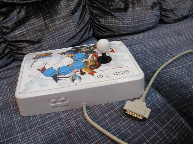
Through the plug I now have direct access to the arcade stick's buttons and joystick.
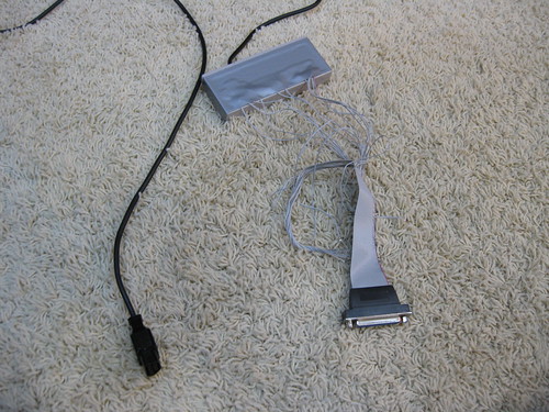
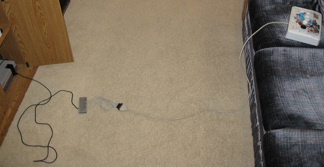
I can build adapters for different consoles out of controllers for the consoles. I run wires from the buttons and dpad/analog stick in the controller to a 25-Pin D-Sub socket. Then I plug my arcade stick’s cord into the controller’s socket. I can play NES games with my arcade stick using the adapter pictured.
LIFE ALTERING NOTICES OF OBSENELY LARGE IMPORTANCE:
I’m not selling any of these. Do not ask.
If you want help, please post about it in this thread. That way, if your problem is fixed the solutions will be available here to help others with the same problem.
There is some risk of making a mistake and breaking something if you undertake this project. If it turns out you break something don't cry at me. I'm allergic to tears and I'll die.
If something in the guide is wrong or confusing, post about it so I have a chance to fix it.
On a related note, I don't think I can stop you from selling anything you make using this guide. On the off chance I somehow could, I give you permission to anyway. Mass produce this stuff in China for all I care. Actually, I’d be rather pleased.
I submit this guide and images into the public domain. Repost it any way you want. I encourage people to make guides for specific sticks or controllers. It will help people who find this generic guide too complicated. I don't need credit, but it makes me feel all special if you do credit me.
ITEMS NEEDED:
Arcade stick:
Get one with arcade style parts, or it isn’t worth the time it takes to mod.
Controller for console:
Just get a cheap one that functions. The buttons and dpad/analog stick are getting replaced so the controller doesn't need to be in good shape to work for this.
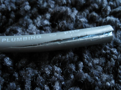
Printer cord/25-Pin D-Sub/parallel cable:
Be wary of “printer” cords as many do not have 25 internal wires. The diameter of the cord must be about 7 mm. If the diameter is about 6 mm it definitely won’t have all the wires. Some 7 mm cords still don’t have all the wires. The flexible-ness of a cord is hard to measure, but you can easily tell the difference between good and bad printer cords if you have a known good or bad cord to compare with.
25-Pin D-Sub cable or parallel cable should include all the wires.
25-pin D-sub socket:
Get this from an old computer, the socket end of a 25-Pin D-Sub/parallel cable, or buy some form mouser. The sockets are super cheap on mouser, especially on orders of 10+, so you may want to buy enough for all the consoles you own or plan to own. Remember you'll want two for every console, since you'll inevitably mod a second controller to get player 2 to shut up about being at a disadvantage...
You’ll have to attach your own wires to the socket if you buy one from mouser.
Wire:
You’ll probably want both solid and braided wire.
TOOLS NEEDED:
Wire strippers
Wire cutters
Ohm meter: The ohm meter will be used as a continuity tester. If you get a reading of less than one Ohm, the wires you are testing are continuous.
Soldering gun
Solder
Flux
Hot glue gun
Glue sticks
Pliers
Screwdrivers
Knife
SOLDERING:
When soldering wires together, take the wire ends you want to solder and twist them all together with pliers before you solder. Don’t just hold them together loosely and solder them.
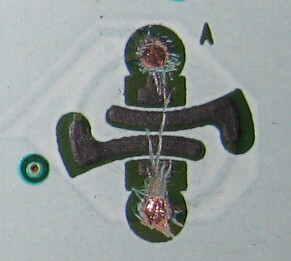
When soldering the controllers circuit board you will need to scrap the insulation off the little pads where the buttons where. Scrape on the pads until they shine. Brush flux on the shining metal to make sure the solder will connect to it well.
PRINTER CORD/25 PIN D-SUB/PARALLEL CABLE:
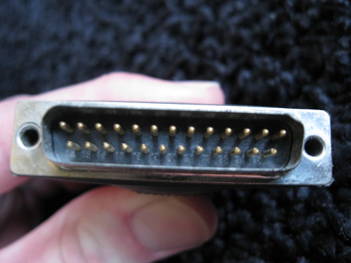
Use wire cutters to cut off one end of the cord. Make sure you are cutting off the correct end.
DO NOT CUT OFF THIS END.
Cut off this end or…
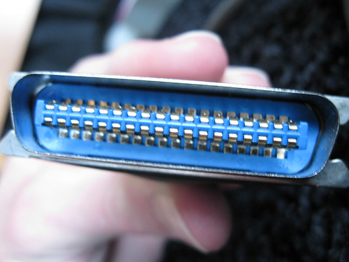
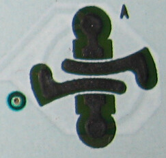
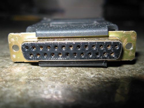
this end depending on which sort of cord you have. If the end you are cutting off looks like the image below, be sure to cut off 6 inches of cord with it so we can use this socket later.
On the end of the cord you just cut, make a 2 inch long slit down the cord. Pull back and cut off all the plastic and metal insulation so the individual wires are accessible.
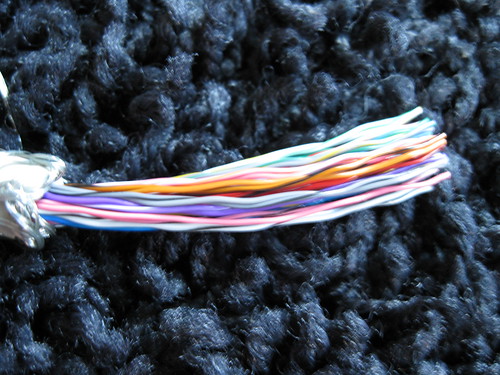
Count the wires in the cable to make sure there are 25 or more. If there are not 25, find another cable and try again. If it does have 25 or more, strip the individual wires. Your wire stripper probably won't have a slot small enough for these tiny wires. Gently pinch the wires in the cutting section of the wire strippers so as to just barely pierce the insulation. Hold the wire strippers pinched and slide the insulation off the end of the wire.
If the socket end was the type I told you to save, repeat the cable slitting and wire stripping for the socket end.
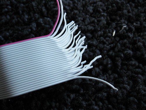
Now we need to know what little wire on this end...
...goes to which pin on this end
It's difficult to place a continuity testing lead on the little pins of the plug. What we'll do instead is put the plug into the socket so we can place the continuity tester on the wires that come from the socket.
Socket came from parallel cord:
If you are using the cut off socket from your parallel cord, you will need to test which socket wire corresponds to which socket hole. Cut a small piece of wire and strip both ends. Place one end in one of the sockets holes. Hold a one lead of the continuity tester to the other end of the wire. Take the other lead of the continuity tester to test the wires coming from the socket.
You can test all the wires individually to find a match, but that is a huge pain. What I do is divide the wires into clumps and test the clumps. If a clump is continuous I break it into smaller and smaller clumps until I find the individual wire that is making the connection. Make a chart showing which socket wire goes to which socket hole.
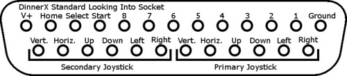
Because the socket is from the same cord as the plug, if you horizontally mirror the connections in the chart you just made you will have a chart showing which plug pin goes to which individual parallel cord wire. This is the “Pin to wire” chart. If you are confused about what I mean by horizontally mirror the connections go down a bit and see how the connections in the DinnerX standard are changed from plug to socket.
Skip down over the Socket from PC section.
Socket came from PC:
If you are using a socket from an old PC you'll need to separate and strip the wires coming from the socket now. The wires separate like twizzlers.
Hold one lead of the continuity tester firmly to a socket wire. Use the other end to test the various wires that were inside the parallel cord. You can test all the parallel cable wires individually to find the match, but it is a huge pain. What I do is divide the printer cord wires into clumps and test the clumps. If a clump is continuous I break it into smaller and smaller clumps until I find the individual wire that is making the connection.
After you’ve found the match for a socket wire, bend the socket wire back so you can keep track of your place.
Make a chart showing which color of parallel cord wire corresponds to which socket wire. This is chart 1.
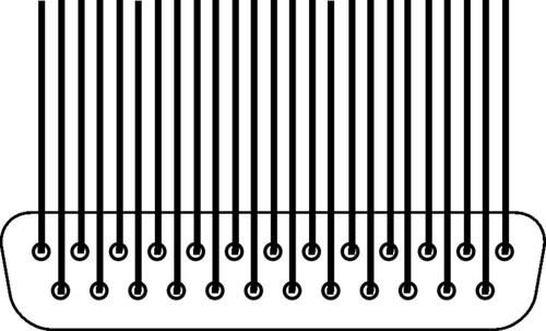
If you got your socket from inside a PC the socket wires should be connected to the socket like this. The rightmost wire goes to the rightmost hole, the second rightmost wire goes to the second rightmost hole and so on. This is chart 2.
Using the two charts it is easy to tell which wire from the parallel cable connects to which socket hole. The plug goes into the socket, so if you horizontally mirror the parallel cable wire to socket hole chart, you create a chart showing which printer cable wires correspond to which plug pins. This is the “Pin to wire” chart. If you are confused about what I mean by horizontally mirror the connections look down a bit at how the connections in the DinnerX standard are changed from plug to socket.
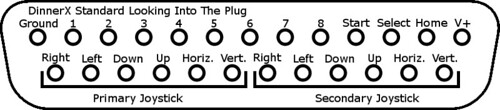
Charts for the connectors:
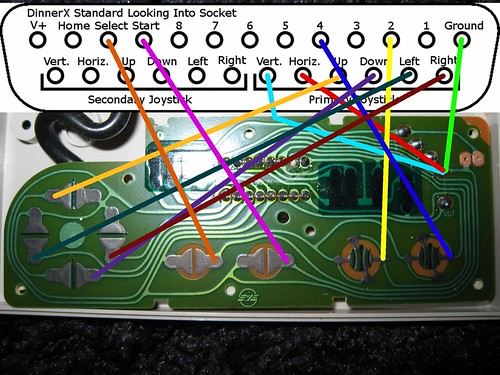
There are many ways the wiring could be done in the next few sections. We just need a wiring path from the controls in the arcade stick to the controls in the controller. I'm going to propose a standard method of connection. That way, people can swap/sell adapters and sticks. It also simplifies making this guide. I’ll call it the DinnerX standard…
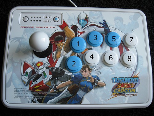
ARCADE STICK:
Buttons in the arcade stick:
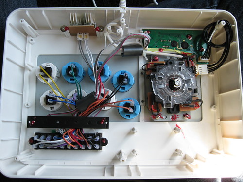
Open up your arcade stick. You need to flip it upside down and set it across two objects so that it is somewhat level and none of the buttons are pressed.
First get cord for the old system out of the road and enlarge the slot in the case so the parallel cord can fit in through it. Use a knife, clippers, or maybe a file, but don’t drill to enlarge the slot. At least for me, drilling did not work and made a bit of a mess.
Notice the cables coming from over by the buttons that plug into the green circuit board. The wires in the cables are connected to the buttons. Cut these button cables in half and strip the wires on the end coming from the buttons.
One of the wires is the common ground. One of the prongs on each button will be connected to this common ground wire. First continuity test between the button prongs until you find two prongs on two different buttons that are connected. That will mean both prongs are the common ground side of their buttons. Make sure none of the buttons are pushed down when you are testing. Now test between one of the common ground prongs and the ends of the wires until you find the common ground wire. Make a note of this.
Next test between the non-common ground prong of a button and the button cable wires. After you find a match, use the “looking into the plug” DinnerX standard and the “Pin to wire” chart to determine which one of the printer cord wires the button wire should be soldered to. Repeat this until all the buttons are connected. Remember the button order is flipped when you are looking at the controller from the back side.
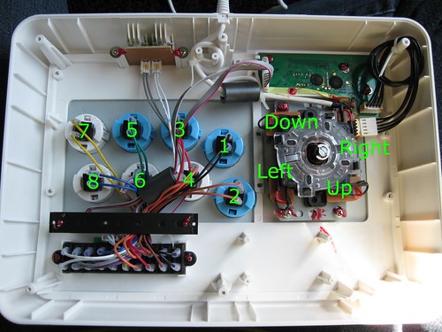
Joystick in the arcade stick:
The joystick is made from four switches. Right now the switches are wired with a common ground. You need to change it so that all the switches are totally separated.
You need to remove all the wires from their little circuit boards. Notice the solder blobs where the wires attach.
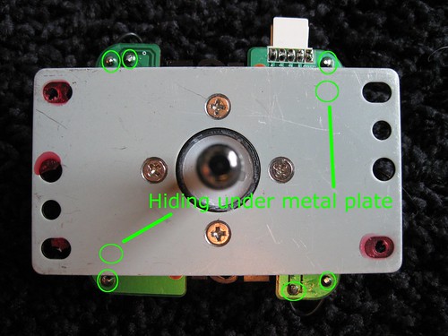
Grab the wires with pliers as close to the solder blob as you can. Heat up the solder with the soldering gun and pull the wire out of the board after the solder liquefies. Be sure to grip as tightly as possible with the pliers, as the insulation on the wire will begin to melt and slide around.
Take one wire both the up switch and down switch and solder them together to a short piece of cut wire. The length of wire coming from this new connection will be the Vert. in the DinnerX standard. It is irrelevant which wires from the up and down switches you use. The joystick wires may be too short to reach one another. If that is the case solder a short piece of wire to one of them and then solder that wire to the other joystick wire.
Take one wire both the left switch and right switch and solder them together to a short piece of cut wire. The length of wire coming from this new connection will be the Horz. in the DinnerX standard. It is irrelevant which wires from the left and right switches you use. The joystick wires may be too short to reach one another. If that is the case solder a short piece of wire to one of them and then solder that wire to the other joystick wire.
Here is a picture showing which joystick switches correspond to which direction. The directions seem all backwardsy because the arcade stick is flipped over and because moving the top of the joystick results in the bottom of the joystick pivoting the opposite direction. Connect the unconnected wire from each switch to the appropriate part of the DinnerX standard.
Leave the arcade stick open for now.
CONTROLLER:
Enclosure:
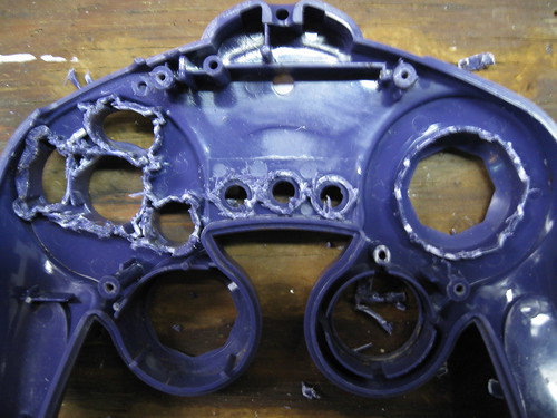
You'll want the controller's circuit board to be in some sort of enclosure. You can use the controller casing like I did for the NES adapter shown at the top of the guide. If you do use the controller casing make sure you snip off the bits on the top of the case that extend down. This makes room for all the connections you will make on the circuit board. Be sure to do this before you connect everything. If you forget, you can do it later, but it’s frustrating.
Also, remember to feed the socket wires through the buttons holes so the case can close up when you are done.
If you don't like the looks or flimsiness of a controller case you can build your own enclosure. You’re on your own there.
Electricity:
How you wire the controller adapter determines how the buttons/joysticks in the arcade stick will correspond to the buttons/dpad/analog stick in the controller. Because there are so many game systems out there, and because there may not be one perfect button configuration for all the games on a system, all I can do is offer some suggestions for layout.
Technical advice:
Sometimes it would be nice to switch which button on the controller is connected to which button on the arcade stick. Simultaneously connecting a button in the arcade stick to multiple buttons in the controller will not work for that. You need to use a single-pole double-throw switch.
You can connect multiple arcade stick buttons to the same button on the controller. If you want to connect the A button to three of the buttons on your arcade stick you can. Each of the three arcade stick buttons could then be used as the A button.
Layout suggestion diagrams:
NES
GC
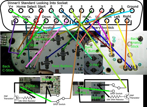
NOTICE: The transistor analog trigger mod idea is based on Zenlocs mod. http://www.made-by-bacteria.com/viewtopic.php?f=42&t=25 I had to flip things around a bit to make it work for this though. I actually haven't got to test it yet. Only a few games really need it.
More specific controller diagrams are to come hopefully. If you’ve got some electrical knowledge you can probably figure out other systems on your own though.
FINISHING UP:
Inside the arcade stick, put electrical tape around all the connections and unused wires to keep everything separated and prevent unwanted connections.
Plug it all together and see if it works. If it doesn't work, bang your head on the wall rapidly, and then use you continuity tester to check that connections are made well and correctly.
After everything works, I recommend you place hot glue over all the connection made on the controller circuit board. These connections tend to break and the glue will help keep them together.
Place the parallel cord in the hole you made in the arcade stick and close up the arcade stick. You might need to use glue to hold the cord in place. For me the cord fit in the slot so tightly I didn’t need any glue.
You're all done! Go play a game. Then live out the rest of your life expectancy doing whatever you wish (within reasonable limitations) and proceed to decompose in a semi-respectable manner.
CREDITS:
Some public domain images from wikipdedia:
http://commons.wikimedia.org/wiki/File:Bipolair-pnp.svg
http://commons.wikimedia.org/wiki/File:SPDT-Switch.svg
http://commons.wikimedia.org/wiki/File: ... atures.svg
Zenloc:
http://www.made-by-bacteria.com/viewtopic.php?f=42&t=25


