The Wiimote has a layout of the NES Gamepad when turned sideways. This allows a NES Gamepad style of gameplay for games such as Metroid Other M, Bit Trip, Blastworks and select other Wii games as well as Virtual Console NES games. A very well thought out design, however the DPad and Action Fire Buttons are a little small. The Wiimote needs larger buttons akin to the original NES Gamepad.
There is the Wii Boss Plastic Shell that fits around the Wiimote.
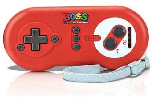
I do not care for plastic shells covering a Wiimote. The mechanical interfaced buttons have a slight delay and wear out the Wiimote button faces. There is a way to incorporate larger buttons and maintain instant response by adding an external controller. I performed a two stage mod to direct connect a NES Gamepad to a Wiimote.
Parts
1. Wiimote - Non Motion Plus which has metal pads and one less item inside.
2. NES Gamepad - This can be any non analog game controller you prefer.
3. D-Sub 9 Pin Male to Female Cable - Prebuilt saves some soldering.
OPTIONAL PARTS - Used for a Future Mod
1. D-Sub 9 Pin Female Connector
2. D-Sub 9 pin Male Connector
3. D-Sub Crimp Female Pins
4. D-Sub Crimp Male Pins
5. Screw lock mounting screw for D-Sub Connectors
6. Two and three pole double on Toggle Switches
- Wii Remote Mod Kit.jpg (219.03 KiB) Viewed 17576 times
The second list of optional parts are for a future Mod such as adding an Arcade stick. For now, the only part needed besides solder is the D-Sub 9 Pin Male to Female cable assembly. One half will be for the Wiimote, the other half for the add on game controller. Be sure the Male end with exposed pins is used with the Wiimote. The Female end will be the cable for the add on game controller. This will allow an easy hookup to future game controllers later on.
Cut the cable in half, cut away about two to three inches of just the outer thick insulation of each cable, then set both cable halves aside. The individual strands will be stripped later when the wires are sized to fit.
Disassemble the Wiimote
There are four screws underneath, two of which are in the battery compartment. A triwing screwdriver is needed or a small slotted jewelers screwdriver can work if placed at an angle. After removing the screws, use a slotted screwdriver to pry the halves apart.
sicknasty413 wrote:http://diy.sickmods.net/Tutorials/Wii/Disassemble_Wiimote/
How To Disassemble The Wiimote
This part may seem difficult. There are 2 clips in the front of the Wiimote that hold the 2 halves together. You may want to take your flathead screwdriver and use it to assist you. But just keep prying and wiggling. It'll give eventually. Try not to break the clips or else you're gonna need to glue your Wiimote back together.
You'll notice a little circular object with 2 wires (red and blue) laying in a white plastic device. That would be the rumble motor. It pulls right out and the wires come out from their little clip. Then the white plastic thing comes right off the PCB. There are clips on both sides. Just unclip one of them and bam. It's off.


Hold the Wiimote with buttons down so none will drop, removing the top shell. Be careful when removing the PCB from the lower housing, the rumble motor will be hanging by two small wires. Remove the B button plastic clip from the lower part of the PCB. Save all the pieces, everything will be used after the mod.
Wiimote Direct Button Mod
The Wiimote has an unusual Printed Circuit Board. Upon close inspection, the traces seem to be buried in a hidden middle layer. This prevents soldering the jumper wires from underneath, the wires go directly onto the button contact pads of the PCB.
CRTGAMER wrote:Be sure to use the Male D-Sub 9 Pin connector cable, the one with the pins exposed inside the plug. This will make it easier to connect standard nine pin controllers.
Before any soldering is performed, the Wiimote housing needs to be scrutinized. There is very little space for a nine strand wire and a very tight fit getting around the PCB and button contacts. I wanted to keep the Classic Controller hookup available and more importantly the Power, Home, + and - Buttons active. The Power button definitely needs to work, without it the Wiimote will not sync.
Cut a little, test fit, then cut a little more
Determine the wire entry point, clearances needed underneath and the best way for each wire to route around the PCB edges. There are notches on the sides of the PCB designed to clear the mounting screws. I removed two of the screw locations, cutting away the legs to make room for each wire. Use a Dremel to cut away plastic.
Drill a hole to the left of the Classic Controller connection point, the hole should be just large enough for a snug fit of the cable. A miniature zip tie wrapped around the wire assembly prevents it from being pulled back out, it also needs room to fit inside the lower housing. Have care that the Red Sync button does not bind against the added wires. Determine which of the various plastic supports needs trimming under the PCB. Some plastic in the upper housing also needs to trimmed, notably the pegs that go in the side notches of the PCB. After all the cutting is completed, I left the two center shell half mounting screw legs intact, the two that go inside the battery compartment.
Identify which side of each pad is the common ground
The easiest way is to run a game with the PCB exposed to test or you can use the pic below as a guide. Touch a wire at each side of a button contact pad to verify. Since the Wiimote A button has the largest contact pad I chose it for the common ground. Touching each button location and use the A button for a common ground confirms which side of each contact pad is hot and which are grounded. I could have used a volt meter to do this, but did not want to risk stray voltage of frying a chip. Make a chart after all the pads are worked out, noting each wire color and location back to the 9 Pin connector plug.
B Button side of PCB
Note that the B button trigger underneath has four contact points, two are hot and two are grounds in a cross hatch pattern. The layout below is when looking at the PCB is with the Battery Compartment to the Right.
Right click for a larger pic
Note the small black circular crosshatched B Button contact on the left. The non Motion Plus Wiimote has metal contacts which is easier to solder. Only one of the hot pads is needed for the B button wire, be sure it is not the ground.
Looking from Left to Right
Ground - Hot - Battery Compartment End
Hot - Ground - Battery Compartment End
A Button side of PCB
See the pic below. The Black wire is ground, the rest are hot leads for the various buttons. Starting from the left, the button contact pads are 2, 1, A and then the four Dpad contacts. The A button pad is the largest, ideal for the common black ground wire. An added benefit with both wires soldered on the A button contact pad, the surface is more level which allows the original button to still function. However, avoid using Wiimote buttons that have wires soldered on the contact pads, the button might get stuck to permanent on.
Right click for a larger pic
CRTGAMER wrote:Solder by pre-tinning each wire with a little bit of solder. Pretin the button contact pads as well, important not to use too much solder.
Solder the lower B button contact pad first. Replace the button clip, decide if the button rubber pad will be left out or not. I did not want to take a chance on the B button staying on so I left out the rubber contact center. Route the wires around the PCB notches as in the pic above and cut each wire to align with each button contact pad. This prevents excess wire looped around getting in the way. The wire has to routed in a way that allows the PCB to fully seat in the lower shell. Take one wire at a time and solder it to the hot portion of each button contact pad. The ground wire is best soldered at the A button ground contact pad.
The Atari 2600 and 7800 Joyport schematic
Wiki wrote:http://wiki.arcadecontrols.com/wiki/Atari_Controller_Interfaces
2600 Pinout
1 = Up
2 = Down
3 = Left
4 = Right
5 = empty
6 = Fire Button
7 = empty
8 = Common (Ground)
9 = empty
7800 Pinout
1 = Up
2 = Down
3 = Left
4 = Right
5 = Right Button
6 = Both Buttons
7 = empty +5 Volt
8 = Common (Ground)
9 = Left Button

In my zeal to ensure the black wire would be ground, I did not take into account of direct hooking up 2600 joysticks. I did not want to resolder the button contact pads for risk of damage. Not a problem, I cut off the molded plug and rewired in a new D-Sub connector rearranging the wires at the plug to conform to the Atari 2600 standard. This allows me to plug in any 2600 compatible joystick without modding, directly into the Wiimote 9 pin plug. Since the Wiimote 2 button is more commonly used for "NES Style" games, it is the best choice for the 2600 Fire button.
Reassemble the Wiimote
If the solder points are kept low, all the button rubber contacts can be placed back in. Luckily the A button is large so it actually works fine even with the wires soldered onto the contact pads. The other modified buttons may also work, but I would not continually press any modded button due to risk of a permanent on position. The Power, Home, + and - buttons are bubble switches, they should function as before.
The Wiimote is ready for an external controller, note the pins are just like a 2600 console.
- Wii Nine Pin Connection Male.jpg (161.74 KiB) Viewed 17576 times
NES Gamepad Mod
A while back I posted a Miracle Piano Guide where I hacked off the cable of a NES Gamepad, I saved it specifically for this mod. The NES GamePad has a DPad, Start, Select and two Action Fire Buttons. Eight buttons plus one ground connection, a total of Nine solder points. This is perfect for a standard Atari 2600 Joyport layout.
Disassemble the NES Gamepad. Remove the five wires by heating up with a solder gun. The chip is a little more tricky, I found it easier to cut the legs off first. After the chip is removed, heat up each pad and suck out the solder pad with a desolder wick or desolder suction tool. You can also just blow into the pad holes while the solder is still liquid. Do not attempt pull the chip legs if the solder is not in a liquid state.
Right click for a larger pic
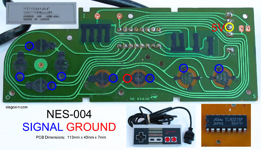
After the chip is removed, cut each trace that leads to a black resistance connection pads. The purpose is to isolate the button contact pads from each other but not from the common ground or the solder points where the chip was removed. The traces are difficult to follow, use an ohm meter to determine the common ground and hot point of each pair of button contact pad.
Right click for a larger pic
I accidently pulled one of the solder pads, fixed with a short white jumper wire. Note the cut traces.
At the wire connection side, use an ohm meter to verify the connections from the button contact pads and PCB traces on the other side. Solder the wires, ensuring the pin layout matches both a 2600 joystick schematic and more importantly matches the modded Wiimote wire layout. Note that the NES Start button makes sense as the Wiimote A button.
NES Button Layout
Pin 1 - NES DPad Up - Wiimote DPad Up
Pin 2 - NES DPad Down - Wiimote DPad Down
Pin 3 - NES DPad Left - Wiimote DPad Left
Pin 4 - NES DPad Right - Wiimote DPad Right
Pin 5 - NES Select - Wiimote B Button
Pin 6 - NES A Button - Wiimote 2 Button
Pin 7 - NES B Button - Wiimote 1 Button
Pin 8 - NES Ground - Wiimote Ground
Pin 9 - NES Start - Wiimote A button

The NES Pad mod has an identical layout to a 2600 joystick. The DPad duplicates the joystick and the NES A button is the same as an Atari Fire button. Since additional buttons are wired in I do not want to take a chance on direct connecting the NES controller to an Atari or Commodore 64. A simple patch cable or 2600 extension cable with just the five buttons and ground wired up will do the trick.
- NES Nine Pin Connection Female.jpg (208.54 KiB) Viewed 17594 times
This mod works beautiful with any sideways "NES Style" controlled game. I maintained the Motion and Shake Sensors as well as the Vibration Motor and Speaker. Games such as Metroid Other M detects the position of the Wiimote during a first person view. In addition, the Classic Controller hookup still works, so I can still plug in any Classic Controller including the Tatsunko Capcom Arcade Stick.
That Arcade stick is teasing me to add a nine pin cable.
Mod References
http://technabob.com/blog/2011/02/28/video-game-controller-alarm-clocks-roger-ibars/
http://pinouts.ru/connector/9_pin_D-SUB_male_connector.shtml
http://wiki.arcadecontrols.com/wiki/Atari_Controller_Interfaces
http://diy.sickmods.net/Tutorials/Wii/Disassemble_Wiimote/
http://www.slagcoin.com/joystick/pcb_wiring.html
Sideways Control Game List
http://www.racketboy.com/forum/viewtopic.php?f=52&t=37984&p=615833#p615833
http://www.giantbomb.com/sideways-wii-remote-gameplay/92-6361/games/
Future Add on controllers
The Wiimote has a nine pin plug ready to accept any modded non analog controller with a matching plug. I can add easily an Arcade stick connection simply by jumping the Arcade button wires to a nine pin plug. No need to mod another Wiimote, the plug makes it more versatile.
A huge range of controller possibilities
I chose the standard Atari 2600 layout, this allows more controller options. In addition to the custom NES Gamepad, I can immediately plug in any of the wide range of Atari 2600 Joysticks. By adding a simple custom built nine pin crossover cable, and depending on voltage requirements, I might even be able to incorporate a Sega Genesis gamepad into the Wiimote. As for the modded NES gamepad, adding a custom nine pin crossover cable makes it a two button Atari 7800 controller.
http://www.rogeribars.com/

All 2600 Joysticks direct plug right in, Sideways Wiimote games that use the 2 for fire work great.
Try playing "NES Control" Wii games with a 2600 Wico!