NES R.O.B Interactive Mod Guide with Updated Repair Info
Posted: Fri Nov 05, 2010 12:26 am
NES R.O.B Interactive Mod Guide
Or how to kill the value of your collectible with a Mod.
Updated, posted a common needed repair in the reply below.
My other controller mods:
Arcade Controller Mod Guide: Home System Adaption
Arcade Spinner Mod: Tempest Inexpensive Method
Twin Stick Mod Guide: Console Arcade Method
For a great FPS controller get an EdgeFX.
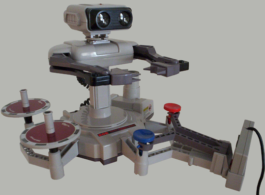
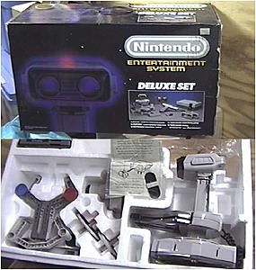
I bought this little robot a few months ago on a very lucky chance buy. Brand new condition, no scratches at all. Only twenty five dollars in a Deluxe Set box. Only the robot and accessories was in that original NES box. Lucky the thrift store also had a NES Zapper in the glass display case for five bucks. The start of my NES collecting! The entire story is HERE.
My main gaming TV is a HD CRT. As in Lightguns needing a regular CRT, ROB is now blind. Dreamcast got a reprieve with a VGA Lightgun setup. But poor ROB doesn't see that VGA screen either. I can use the bedroom TV. But with only two games, a very limited gameplay of this NES robot. I don't even have the Stack-Up accessories! So how to get use out of this robot so its not just a dust collector?

Time to go interactive. A full control of all of ROB's functions. No, not just the silly CRT screen flash, but a direct control!
The Breakdown
Three motors inside ROB.
Motor 1 - Up and Down
Motor 2 - Open and Close Arms.
Motor 3 - Rotate Left and Right.
Two of the motors are behind the arms, a pain to put back together. Glad I pulled that arm cover with ROB upside down. The real headache is in order to change directions, the polarity of the motors are reversed. Tricky, half the switches would have to be positive, other half negative. This rules out a regular gamepad with only one closing circuit at each pad and button. A work around is using Diodes to act as an electrical check valve. There also looks to be resistors attached on each motor terminal, a slight reduction in voltage to reduce the speed. The biggest downfall is isolating the individual PCB traces in the base of the robot. A decision if I should "cut the cord" on ROB's original function of using the sensor screen flash in Gyromite?

First Fail
My first attempt didn't work out. I was trying to line up diodes to allow the reversible motors of the NES robot to work directly with a NES controller. No luck, looks like I'll have to go with a two pole 3 position momentary toggle switch. Have to isolate both positive and negative to reverse the direction. Three Momentary ON-OFF-ON switches needed. I would have loved to use a NES original controller. Only single pole contacts under the NES buttons. There is that video clip on Youtube, probably used relays which would be expensive for this little hobby mod. Don't worry ROB, I haven't given up, the toggles are the answer.
 Nintendo R.O.B. Mod: Manual Control
Switch the Switch
Picked up three miniature toggle switches. Three position ON-OFF-ON normal off with both sides momentary on. Convenient spring loaded back to off. Two poles to control both positive and negative leads. A simple matter of reversing leads at the switch for the opposite direction.

Need an eight strand cable, Frys has a 6 foot Nine Strand. Perfect, I was lucky to get this. No peg hook of the sku, cable was laying on the bottom shelf. I think the same cable I returned from the Diode attempt earlier in the week.
A hunt for a controller base.
FRYs had project boxes, but all the wrong size and too expensive. Home depot more promising, but the blue outlet power boxes were too big. A visit to Industrial Liquidators showed a couple interesting boxes. I almost bought a deep red transparent case for a LED clock, but didn't feel right. In desperation, I was about to use a cat food or lizard worm can. The bottom had an interesting pattern and beautiful anodized copper color, but the wrong shape. Don't laugh, would have been a unique base. I thought of regular game controllers which won't take the toggle switches, the button holes are too big. Come to think of it, I really wanted the size of a NES controller.

Okay rummaging through my junk boxes I found an old after-market Beeshu Zipper NES pad. Before anyone yells, the Zipper was dead. Bought ages ago at Swap Meet with the cord cut. I could have gotten a new cord for it, but chance of a mismatch not worth frying my Toaster NES.
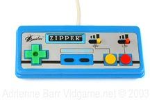
The bottom would now be the top. I could have just thrown electrical tape to cover the button holes. Wanted a cleaner look even if its the bottom. I removed and dremeled all controller buttons to ⅛" thickness. I didn't want messy glue running off, so I electrical taped the buttons from the inside. All buttons are flush, becoming the new bottom and sits flat on the table. Another simple fix would be a piece of sheet metal or plastic, but I like the novelty of the now non-functioning carnival color buttons.
Destroy the Robot
Photos of the Mod at the bottom.
Moment of truth, drilling a small hole at the back of ROB for the controller cable. The big commitment, cutting the cords inside from the PCB. I left a little hanging if I ever did want to reverse the Mod. To verify the connections, a simple test of two wires at a time to the battery box.
Easy ones
Battery - Red and Black
Spin - Yellow and White
Separate plug
Claws - Red and Brown
Up/Down - Orange and Yellow
Tempted to power the LED, but would only work in one polarity, half the movements. Oh well, save on the battery a little.
I ran simple jumpers right at the toggle switches to reverse the polarity. An easy way to reduce the amount of wires. Staged all the wires into the switch terminals before taking out the pencil soldering Iron. A magnifying station helps to prevent shorts in those tiny terminals.

Precut shrink tube and placed on wire before soldering up the splices. A zip tie at the insulation prevents the controller cable from being yanked out.
After the photos were done, I did one more minor mod. I spun the one toggle switch ninety degrees to match the spin direction of ROB.
New Gameplay
First, ROB is now independently controlled. Now can be used as a wired remote control robot toy. Robot works flawlessly, instant response to the toggles. But now a new take on the Gyromite game. Okay how many have cheated at Gyromite? Ignoring the robot and just grabbing the second controller to drop the pillars. This mod gets ROB another chance, depending how well a HUMAN second player can make the little robot drop the Gyro on the game controller rail. Or ever better, try to do this solo for a frenzied play. Don't let that Gyro top fall!
-2.png)
I have an extra set of rails to hold a NES second controller. Two controllers with matching holders all operated by the game indirectly through the robot. Not sure of any games that use the A and B buttons only. Imagine trying to balance the pie plates working both mounted controllers with this modded ROB.
Now to see if the Armatron dexterity will beat R.O.B.'s speed.
A quick note about the Radioshack Armatron. An 80s engineering genius design! Only one motor controlling a bunch of ring gears inside. The levers would engage various gears to cause a different function. Spin the Arm and Claw, Raise and Lower, as well as Multiple Pivot Points. 12 selections in all!

Related links
Gyromite NES Import Adaptor Guide
How I found my R.O.B.
Repairing R.O.B. (NES)
A great Armatron site
Or how to kill the value of your collectible with a Mod.
Updated, posted a common needed repair in the reply below.
My other controller mods:
Arcade Controller Mod Guide: Home System Adaption
Arcade Spinner Mod: Tempest Inexpensive Method
Twin Stick Mod Guide: Console Arcade Method
For a great FPS controller get an EdgeFX.
I bought this little robot a few months ago on a very lucky chance buy. Brand new condition, no scratches at all. Only twenty five dollars in a Deluxe Set box. Only the robot and accessories was in that original NES box. Lucky the thrift store also had a NES Zapper in the glass display case for five bucks. The start of my NES collecting! The entire story is HERE.
My main gaming TV is a HD CRT. As in Lightguns needing a regular CRT, ROB is now blind. Dreamcast got a reprieve with a VGA Lightgun setup. But poor ROB doesn't see that VGA screen either. I can use the bedroom TV. But with only two games, a very limited gameplay of this NES robot. I don't even have the Stack-Up accessories! So how to get use out of this robot so its not just a dust collector?
Time to go interactive. A full control of all of ROB's functions. No, not just the silly CRT screen flash, but a direct control!
The Breakdown
Three motors inside ROB.
Motor 1 - Up and Down
Motor 2 - Open and Close Arms.
Motor 3 - Rotate Left and Right.
Two of the motors are behind the arms, a pain to put back together. Glad I pulled that arm cover with ROB upside down. The real headache is in order to change directions, the polarity of the motors are reversed. Tricky, half the switches would have to be positive, other half negative. This rules out a regular gamepad with only one closing circuit at each pad and button. A work around is using Diodes to act as an electrical check valve. There also looks to be resistors attached on each motor terminal, a slight reduction in voltage to reduce the speed. The biggest downfall is isolating the individual PCB traces in the base of the robot. A decision if I should "cut the cord" on ROB's original function of using the sensor screen flash in Gyromite?
First Fail
My first attempt didn't work out. I was trying to line up diodes to allow the reversible motors of the NES robot to work directly with a NES controller. No luck, looks like I'll have to go with a two pole 3 position momentary toggle switch. Have to isolate both positive and negative to reverse the direction. Three Momentary ON-OFF-ON switches needed. I would have loved to use a NES original controller. Only single pole contacts under the NES buttons. There is that video clip on Youtube, probably used relays which would be expensive for this little hobby mod. Don't worry ROB, I haven't given up, the toggles are the answer.
Switch the Switch
Picked up three miniature toggle switches. Three position ON-OFF-ON normal off with both sides momentary on. Convenient spring loaded back to off. Two poles to control both positive and negative leads. A simple matter of reversing leads at the switch for the opposite direction.
Need an eight strand cable, Frys has a 6 foot Nine Strand. Perfect, I was lucky to get this. No peg hook of the sku, cable was laying on the bottom shelf. I think the same cable I returned from the Diode attempt earlier in the week.
A hunt for a controller base.
FRYs had project boxes, but all the wrong size and too expensive. Home depot more promising, but the blue outlet power boxes were too big. A visit to Industrial Liquidators showed a couple interesting boxes. I almost bought a deep red transparent case for a LED clock, but didn't feel right. In desperation, I was about to use a cat food or lizard worm can. The bottom had an interesting pattern and beautiful anodized copper color, but the wrong shape. Don't laugh, would have been a unique base. I thought of regular game controllers which won't take the toggle switches, the button holes are too big. Come to think of it, I really wanted the size of a NES controller.
Okay rummaging through my junk boxes I found an old after-market Beeshu Zipper NES pad. Before anyone yells, the Zipper was dead. Bought ages ago at Swap Meet with the cord cut. I could have gotten a new cord for it, but chance of a mismatch not worth frying my Toaster NES.
The bottom would now be the top. I could have just thrown electrical tape to cover the button holes. Wanted a cleaner look even if its the bottom. I removed and dremeled all controller buttons to ⅛" thickness. I didn't want messy glue running off, so I electrical taped the buttons from the inside. All buttons are flush, becoming the new bottom and sits flat on the table. Another simple fix would be a piece of sheet metal or plastic, but I like the novelty of the now non-functioning carnival color buttons.
Destroy the Robot
Photos of the Mod at the bottom.
Moment of truth, drilling a small hole at the back of ROB for the controller cable. The big commitment, cutting the cords inside from the PCB. I left a little hanging if I ever did want to reverse the Mod. To verify the connections, a simple test of two wires at a time to the battery box.
Easy ones
Battery - Red and Black
Spin - Yellow and White
Separate plug
Claws - Red and Brown
Up/Down - Orange and Yellow
Tempted to power the LED, but would only work in one polarity, half the movements. Oh well, save on the battery a little.
I ran simple jumpers right at the toggle switches to reverse the polarity. An easy way to reduce the amount of wires. Staged all the wires into the switch terminals before taking out the pencil soldering Iron. A magnifying station helps to prevent shorts in those tiny terminals.
Precut shrink tube and placed on wire before soldering up the splices. A zip tie at the insulation prevents the controller cable from being yanked out.
After the photos were done, I did one more minor mod. I spun the one toggle switch ninety degrees to match the spin direction of ROB.
New Gameplay
First, ROB is now independently controlled. Now can be used as a wired remote control robot toy. Robot works flawlessly, instant response to the toggles. But now a new take on the Gyromite game. Okay how many have cheated at Gyromite? Ignoring the robot and just grabbing the second controller to drop the pillars. This mod gets ROB another chance, depending how well a HUMAN second player can make the little robot drop the Gyro on the game controller rail. Or ever better, try to do this solo for a frenzied play. Don't let that Gyro top fall!
I have an extra set of rails to hold a NES second controller. Two controllers with matching holders all operated by the game indirectly through the robot. Not sure of any games that use the A and B buttons only. Imagine trying to balance the pie plates working both mounted controllers with this modded ROB.
Now to see if the Armatron dexterity will beat R.O.B.'s speed.
A quick note about the Radioshack Armatron. An 80s engineering genius design! Only one motor controlling a bunch of ring gears inside. The levers would engage various gears to cause a different function. Spin the Arm and Claw, Raise and Lower, as well as Multiple Pivot Points. 12 selections in all!
Related links
Gyromite NES Import Adaptor Guide
How I found my R.O.B.
Repairing R.O.B. (NES)
A great Armatron site

